Hem Block Dies
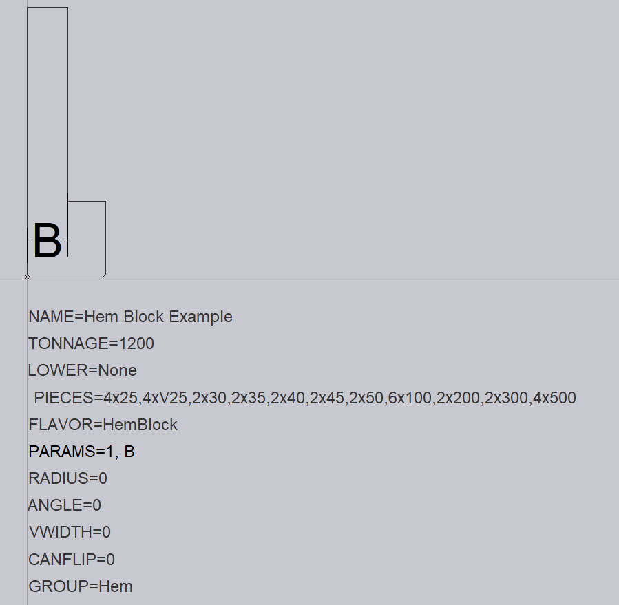
Below, we can see a sample Hem Block Die DXF drawing. An origin reference point will need to be placed at the mounting point on the side profile of the tool.
This tool is a flat seaming die that is mounted in front of, or behind another die. For example, the FWZ or ZDL tools in the Trumpf tooling system are HemBlock tools. These tools might be mounted in front of the existing die (like the FWZ tools) or behind the existing die (like the ZDL tools). Where it mounts is decided by where the origin point is placed. If the origin point of the tool is at the bottom right of the tool shape, then it mounts in front of the die. If the origin point is at the bottom left, then it mounts behind the die.

The following text entities are required for a Hem Block Die:
NAME – This is the name given for the tool.
TONNAGE – This is the tonnage of the tool in kN.
LOWER- This is the Lower punch valency of the tool. For a Hem Block, this can be set to None.
PIECES – These are the required tool lengths. These are separated by a comma, and if more than one is required, we can use a multiplier to specify the value required.
FLAVOR=HemBlock – This marks this tool as a Hem Block.
PARAMS – This text provides some metrics that are required for correct simulation, shown as B in the image above. See below for further PARAM explanation.
RADIUS – This is the radius of the tool. For Hem Blocks, this is set to 0.
ANGLE – This is the angle of the tool. For Hem Blocks, this is set to 0.
V-WIDTH – This is the V-width of the tool. For Hem Blocks, this is set to 0.
CANFLIP – If the tool can be flipped when mounted, this should be set to 1.
GROUP – This can be used to specify the tool group that this tool would belong to. In this case, it is Hem.
PARAMS Explanation
Two parameters are required to define the hemming block.
A – The first parameter defines the hemming position and whether this block should be used in front of the die or behind the die. 0 = front and 1 = back. The above example shows that the block can be used in front of the die.
B – The other parameter is the hemming displacement which is the I-axis movement. This is shown as B in the image above.

