How Can We Help?
Assemblies
Preparing an Assembly
- Open an assembly by using File > Open or using the keyboard shortcut O.
- Use the keyboard shortcut X to explode the assembly. The assembly breaks up into individual bending parts.
- Execute the workflow for the respective bending parts.
After an assembly has dissolved, a message is displayed indicating the total number of parts found in the assembly as well as the number of different parts.

The 3D model is automatically categorised after importing.
| Model | Meaning |
| Assembly | A part depicting an assembly (consisting of different parts or modules). |
| Surface Model | A surface model contains a group of surfaces connected with each other. Some surface models can be analysed and converted into metal parts. |
| Metal Model | Models containing layers and bending sections with one and the same sheet thickness. A metal model can be unfolded to one area or used as a basis for bending processing. |
| Laser Model | This is a special type of metal model without bends. Only laser cutting or punching is required for such models. |
| Tube Model | A tube model is created on each of the layers from an extruding tube section with end cuts, rims and holes. |
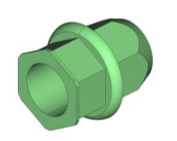
| Component | Depicts a non-metal component such as e.g. a nut, a bolt, or a rivet, … These components are not used for manufacturing processing but only to generate bills of material. |
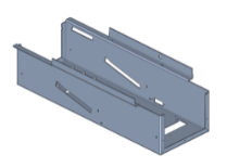
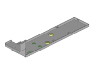
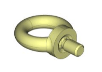
The symbols are displayed in the software next to the file name. Different colours are displayed in the 3D view to categorise the models. The following standard colours are used:
- Blue-Grey: Surface model, assembly, tube model
- Grey: Metal Model
- Yellow: Components which have not yet been identified
- Green: Components which have already been identified
