The Bend Status Navigator
The bend step navigator is the central tool to review the bend solution. As changes are made to the punch, die, sequence, or gauge configurations, the bend navigator is immediately updated with the new status. This immediate feedback makes it easy to experiment with different configurations without having to issue a recompute command each time.
Bend Status Navigation

| Number | Description | Meaning |
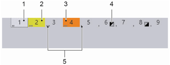
| 1 | Current bend | The current bend is displayed with an outlined box and is hatched. |
| 2 | Bend with warning | Bends with a warning are displayed with the colour yellow. |
| 3 | Bend with error | Bends with an error are displayed with the colour orange. |
| 4 | Symbol | On the right of the bend number, a symbol points to some special features. These are explained further down the article with icons. |
| 5 | Tool Station | The spots beside the bending number indicate the respective tool station. They are only visible if the bending part has more than one tool station. |
| 6 | Tool Setup | If more than one setup is defined for a bending part, bending steps are then bordered with various colours for each setup. |
Bend Simulation Navigation

| Number | Description | Meaning |
| 1 | Run simulation | The simulation will be run from the current position. |
| 2 | Stop simulation | The simulation will be stopped at the current position. |
| 3 | Reset simulation | The simulation is reset to the start. |
| 4 | Slider | The slider displays the current position of the simulation. The position of the slider can be changed by keeping the left mouse button pressed. A tooltip with the current bending operation appears. |
| 5 | Display/Hide Bending Status | Expand to show a detailed overview of the bending steps. |
Bend Status Navigation – Expanded View

| Number | Description | Meaning |
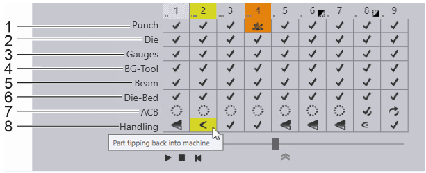
| 1 | Upper Tool | Information about the upper tool used for the current bend. |
| 2 | Lower Tool | Information about the lower tool used for the current bend |
| 3 | Back Gauge | The status of the back gauge positioning. |
| 4 | Back Gauge and Tool | Information about collisions between the back gauge and the tool. |
| 5 | Beam | The status of the beam is displayed here. |
| 6 | Press Table | Information about collisions with the press table is displayed here. |
| 7 | ACB | ACB information is displayed here. |
| 8 | Part Handling | Messages and directives on parts handling are displayed here. |
The ‘Punch’ row
The Punch row of the bend navigator displays information about the punch used for this bend and shows if there are any punch-related warnings or errors.
The ‘Die’ Row
The Die row of the bend navigator displays information about the die used for this bend and shows if there are any die-related warnings or errors.
The ‘Gauges’ row
The Gauges row of the bend navigator displays information about the back gauges used to reference the part during bending, and also any gauge-related warnings or errors.
The ‘Beam’ row
The Beam row of the bend navigator displays errors related to the beam (press ram).
The ‘Die-Bed’ row
The Die-Bed row of the bend navigator displays errors related to the die-bed and table.
The ‘ACB’ row
The ACB row of the bend navigator displays warnings and errors related to the angle measurement system.
The ‘Handling’ row
The Handling row of the bend navigator displays information about part-handling. This includes information on how the part should be rotated or flipped between bends, and also warnings for situations where the part centre-of-gravity falls behind the bending axis (part tip-back warning).
As you make changes to the punch, die, sequence, or gauge configurations, the bend navigator is immediately updated with the new status. This immediate feedback makes it easy to experiment with different configurations without having to issue a ‘recompute’ command each time.

