Z-Bend Punch
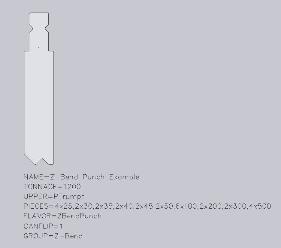
Below, we can see a sample Z-Bend punch DXF drawing. A side view profile of the tool is drawn. An origin reference point will need to be placed at the mounting point on the side profile of the tool.
For a Z-Bend punch, there should be a text entry like this in the DXF file: FLAVOR=ZBendPunch
In addition, the tool should be drawn so that the central flat span goes from bottom-left to top-right. In other words, the orientation should be as shown in the image below, and not the flipped orientation of this:

The following text entities are required for a Z-Bend punch:
NAME – This is the name given for the tool.
TONNAGE – This is the tonnage of the tool in kN.
UPPER – This is the upper punch valency of the tool.
PIECES – These are the required tool lengths. These are separated by a comma, and if more than one is required, we can use a multiplier to specify the value required.
FLAVOR=ZBendPunch – This text is required to mark the tool as a Z-Bend Punch.
CANFLIP – If the tool can be flipped when mounted, this should be set to 1.
GROUP – This can be used to specify the tool group that this tool would belong to. In this case, it is Z-Bend.

