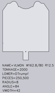
Creating Tools
Bend tools can be exported as DXF or ARV and can be imported from a DXF or ARV format.
All tools can be exported in a DXF format; however, only single upper tools and single lower tools can be exported as an ARV format. More tool-ARV files can be imported than exported. ARV-import exceptions are complex special tools such as hinge tools.
Create a Tool Using DXF
To create a DXF file for a new tool, a DXF file of an existing tool must be processed. To do this follow the next steps:
Export existing tool as a DXF.
Open the exported DXF file.
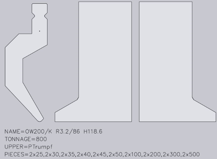
Edit the DXF file to adjust the exported tool to the new tool.
The DXF file must contain the following:
- A closed form (of lines, arcs, polylines) shows the side profile of the tool. In the drawing, this form must be at the closed polyline that is furthest to the left.
- A point which marks the reference point of the tool. This point must be located somewhere inside the polyline of the closed profile and indicates the point from which the height of the tool is measured.
- A front view is required for each tool which is not a simple rectangle in the front. These are typically left or right-horn tools but can also be user-defined tools.
- Each front-view drawing must appear on the right-hand side next to the sectional drawing, be horizontally aligned and have the same height as the sectional drawing. Currently, only the horn view is supported.
- Additional information about the tool is displayed using text strings. See below to view the text strings that are recognised.
If multiple tools with special forms, such as horn tools, are present, a text with the number of the quantity must be entered.
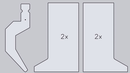
A front view can be added for window tools.
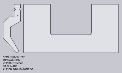
Export drawing as a DXF.
Import DXF.
Create tool ARV file for the import to the machine.
Activate the created ARV file in the machine.
Main Text Strings
NAME=UT200/K R3.2/86 CUSTOM-A – Specifies the tool name; this is required.
TONNAGE=800 – Specifies the maximum load of the tool in kN/m; this is required to avoid showing incorrect tool overload errors.
UPPER=PTrumpf – Specifies the connection type of the upper tool to the press beam; the following connection types are supported: PTrumpf, PAmada and PEHT
LOWER=DTrumpf – Specifies the connection type of the lower tool; the following connection types are supported: DTrumpf, DAmada30, DAmada60, DAmadaF, DAmada2V, DAmadaQuick, DAmada90, DEHT and DAmada120.
PIECES=2×25,30,45,50,2×100,200,4×500 – This specifies the standard quantity for this tool, whereby the quantity for the left and right horn tools are defined by their sectional drawing. The list consists of several comma-separated quantities and, optionally, a quantity multiplier may be added in front of these. In this case, the text states the following tool quantity: 2 pcs with 25 mm, 1 piece with 30 mm, 1 piece with 45 mm, 1 piece with 50 mm, 2 pcs with 100 mm, 1 piece with 200 mm and 4 pcs with 500 mm.
Special Tools
With Tool import, different types of special tools can be detected. These must be specified by a text string in the DXF file:
FLAVOUR=XYX
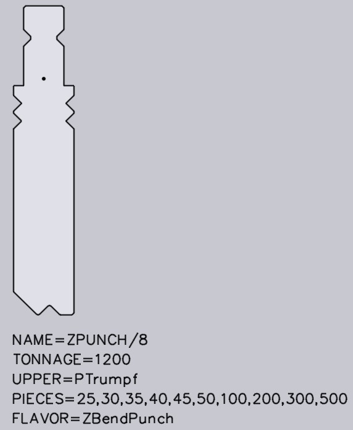
Z-Upper Tools
For a Z-upper tool, a text string with the following format must be available in the DXF file:
FLAVOR=ZBendPunch
The tool should be drawn so that the medium flat span width runs from the left bottom to the right top.
Z-Lower Tools
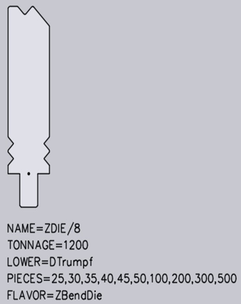
For a Z-lower tool, a text with the following format must be available in the DXF file:
FLAVOR=ZBendDie
The tool should be drawn so that the medium flat span width runs from the left bottom to the right top.
Upper Tool Adapter
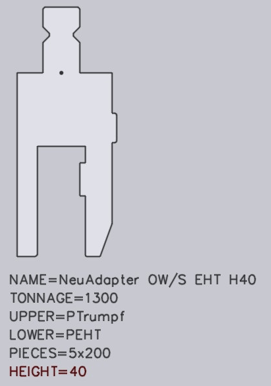
For an upper tool adapter, a text with the following format must be available in the DXF file.
UPPER=PTrumpf – Identifies the upper mounting type (PTrumpf is used if the adapter is mounted on a Trumpf machine).
LOWER=PEHT – Identifies the bottom mounting type, such as the type of upper tool which is mounted on the adapter.
HEIGHT=64 – Indicates the effective working height of the adapter. This is necessary because Easy Programming does not automatically detect the height of the adapter.
Holder
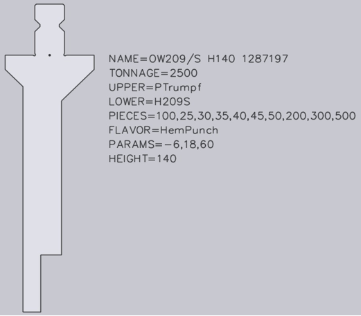
Holders are configured in the same way as an upper tool adapter. However, certain holders, such as a UT209/S, are also folding tools which are used to press down a hem. For these special holders, additional texts must be contained in the DXF file.
SPLFLAVOR=HemPunch – Identifies the adapter as a folding tool.
PARAMS=-6,18,60 – Identifies three parameters required for the correct simulation of the folding process. These parameters will be marked in the image below as (A), (B) and (C).
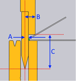
- The first parameter (A) defines how far the flat vertical area of the tool is located behind the bending line. In this case, the value is negative, because the flat vertical area is located in front of the bending line.
- The second parameter (B) defines how far the peak of the fold is located in front of the bending line.
- The third parameter (C) defines the vertical clearance from the punching peak to the folding peak point.
Special Lower Tools
When importing, if a message such as ‘Radius not specified’ or ‘Angle not specified’ it is due to the shape of the tool not being analysed and the V-width, radius and angle cannot be detected as a result. In this case, Radius=, Angle=, and V-width= must be added as text.
