Radius Holders
Below, we can see a sample Radius Holder DXF drawing. An origin reference point will need to be placed at the mounting point on the side profile of the tool.
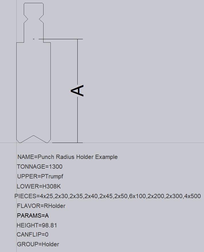
The following text entities are required for a Radius Holder:
NAME – This is the name given for the tool.
TONNAGE – This is the tonnage of the tool in kN.
UPPER – This is the upper punch valency of the tool.
LOWER – This is the lower valency of the tool to be mounted into the holder.
PIECES – These are the required tool lengths. These are separated by a comma, and if more than one is required, we can use a multiplier to specify the value required.
FLAVOR=RHolder – This text marks the adapter as a radius-shaft holder.
PARAMS – This is the height of the tool to be output into NC code, measured from the bottom of the tool to the mounting point (shown as A in the image).
HEIGHT- This is measured from the origin to the inverted V of the holder.
CANFLIP – If the tool can be flipped when mounted, this should be set to 1.
GROUP – This can be used to specify the tool group that this tool would belong to. In this case, it is Holder.