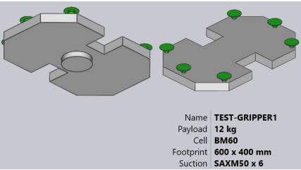
See the simple drawing shown, which defines a gripper and can be saved as a DXF file to import back inside the Gripper inventory.
Here are some important points about how the DXF is drawn:
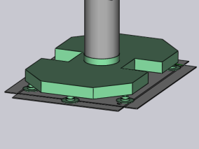
The origin of the drawing (0,0) corresponds to the robot wrist centre. You can see this represented by a point and circle in the figure. (Both the point and the circle are not needed for the gripper import since the gripper centre is implicitly always at the origin).
This drawing also has some POINT entities representing each of the suction cup locations. Again, these are primarily for making the drawing clear and are not used by the gripper importer (the suction cup positions are specified by text entities).
The actual plate shape is drawn as closed POLYLINE entities. If you have other polylines inside the outer one, they become holes in the plate.
Table of Contents
Manage Cookie Consent
To provide the best experiences, we use technologies like cookies to store and/or access device information. Consenting to these technologies will allow us to process data such as browsing behaviour or unique IDs on this site. Not consenting or withdrawing consent, may adversely affect certain features and functions.
Functional
Always active
The technical storage or access is strictly necessary for the legitimate purpose of enabling the use of a specific service explicitly requested by the subscriber or user, or for the sole purpose of carrying out the transmission of a communication over an electronic communications network.
Preferences
The technical storage or access is necessary for the legitimate purpose of storing preferences that are not requested by the subscriber or user.
Statistics
The technical storage or access that is used exclusively for statistical purposes.The technical storage or access that is used exclusively for anonymous statistical purposes. Without a subpoena, voluntary compliance on the part of your Internet Service Provider, or additional records from a third party, information stored or retrieved for this purpose alone cannot usually be used to identify you.
Marketing
The technical storage or access is required to create user profiles to send advertising, or to track the user on a website or across several websites for similar marketing purposes.