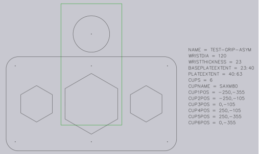
Slightly more complex grippers can be modelled using a separate BASEPLATE layer. Create a layer named BASEPLATE in the DXF file, and draw some closed POLYLINE shapes in that layer. Then this layer can have separate Z extrusion limits specified by the BASEPLATEEXTENT key.
Click on Related when a drawing is being edited.
Click on the Layers menu
The Layer editor dialogue (shown below the centre) is displayed. Here you can add new layers, rename them, and set colours and line styles.
In the drawing, clicking on an entity allows you to change the layer of that entity (see image above right). This selector appears only if there are multiple layers in the drawing.
After editing the drawing using these tools, save the drawing in DXF Format.
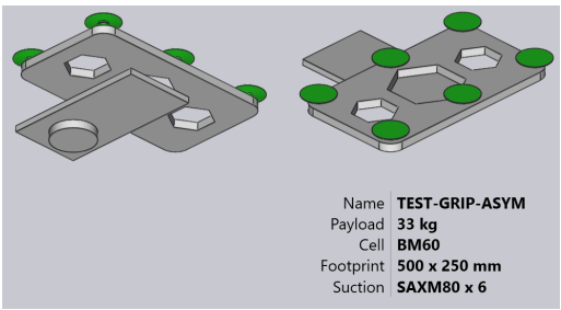
Note: For this gripper, the wrist extends from Z=0 to Z=23. Then, the base plate (green) extends from Z=23 to Z=40, as indicated by the BASEPLATEEXTENT key. Finally, the actual gripper plate (holding the suction cups) extends from Z=40 to Z=63, as indicated by the PLATEEXTENT key.
Note that the gripper plate also has some hexagonal holes in it.
Table of Contents
Manage Cookie Consent
To provide the best experiences, we use technologies like cookies to store and/or access device information. Consenting to these technologies will allow us to process data such as browsing behaviour or unique IDs on this site. Not consenting or withdrawing consent, may adversely affect certain features and functions.
Functional
Always active
The technical storage or access is strictly necessary for the legitimate purpose of enabling the use of a specific service explicitly requested by the subscriber or user, or for the sole purpose of carrying out the transmission of a communication over an electronic communications network.
Preferences
The technical storage or access is necessary for the legitimate purpose of storing preferences that are not requested by the subscriber or user.
Statistics
The technical storage or access that is used exclusively for statistical purposes.The technical storage or access that is used exclusively for anonymous statistical purposes. Without a subpoena, voluntary compliance on the part of your Internet Service Provider, or additional records from a third party, information stored or retrieved for this purpose alone cannot usually be used to identify you.
Marketing
The technical storage or access is required to create user profiles to send advertising, or to track the user on a website or across several websites for similar marketing purposes.