Starting with a 3D Part in Sheet Metal Mode (Press 3 on the keyboard), the software will show forms and components which can be trained in the software for additional stage processing.
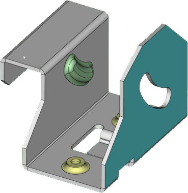
In this example you can see that we have two unique forms in the part which are coloured Green and Yellow where Yellow indicates that the form is not currently setup in the system.
Clicking on the form will give you 3 options to either identify the feature, Make a hole where the feature is or to delete the feature.
Clicking to Identify the feature will bring up a dialog box where you can see a list of all the forms that are already setup along with options to setup the new form that was selected.
The main setup consists of the following.
Name where you can enter in a unique name to identify the form.
Identifier where you can enter in an ID reference number for the form.
Output Layer (DXF) where you can write the feature out to a specific layer in a flat form DXF.
Once the parameters are entered click the add button and the identified form will change colour to green to show it is configured. Hovering your mouse over the form will also display the name that has been assigned to it.
In addition to the identify feature you can also select the following options, make a hole which will look at the outer perimeter of the form and will cut it out of the part or delete the feature which will remove the feature from the geometry leaving the plane intact.