Editing the Gauges
The first bend in every side (or section) has a gauging position that is computed automatically by Flux. You can examine or edit this gauging position interactively. To do this:
- Select the first bend in a section (click on the bend number in the fold navigator, or use the PageUp and PageDown keys to switch to that bend).
- When the first bend in a section is selected, the gauges are visible.
- Click on one of the gauges to bring up the Gauges panel.
The panel (shown alongside) has a few different settings and operations:
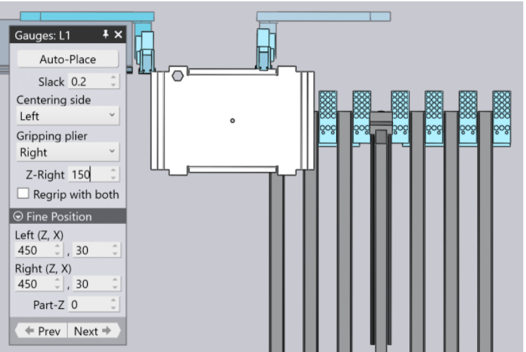
Slack is the extra opening between the gauges (this corresponds to the D Z1-Z2 parameter in the centring settings of the machine). This can be used to open up the gauges slightly to make it easier to insert the part.
Height is the amount the gauges are lifted from the zero position during the centring (the zero position places the flat surface at the corner recess of the gauge at the bottom of the sheet). For some parts, it is useful to adjust the Height to reference against the bottom part of the back gauges. As you adjust this, the gauge moves, and if it collides with the part, the gauge and the offending surface in the part are coloured red. When such a collision happens, the navigator on the top also updates immediately to show the offending bend in red. (You can then open the navigator to inspect the reason for the error).
Auto-place is used to compute automatic positions for the gauges. This is done for all the sides when you switch to the panel-bending mode. However, after you have manually moved the gauge into some position for experimenting, this button is useful to reset the position of the gauges. In actuality, the gauges panel computes a series of alternative positions for the gauges, and each time you click on the Auto-place button, it displays the next feasible position of both gauges.
To get back to the first-recommended gauging position, close the gauges panel (by clicking the X on the top right corner), click on the gauge again and click on Auto-place.
The Gripping plier setting is used to select whether the left or right plier is used to clamp the part
The Next and Prev buttons are used to switch to the other sides of the part; you can then edit the gauging settings for those sides. As you click on these buttons you will see the part simulation immediately updated to display that side in the centring position.
The Fine Position settings at the bottom are the same as before and are used to position the left and right gauges for the actual centring.
Gauge-X and Gauge-Y are used to fine-tune the position of the gauges interactively. As you use these to adjust the gauge positions, the gauges move and the collision status is updated.
Z-Right Setting controls where the plier is relative to the part centre. As you move the plier in Z, the X position of the plier is computed automatically.