How Can We Help?
Layers
Default Layer Configuration
The default layer configuration can be set to show different elements of a part when drawing. For example, different colours or line types can be used to differentiate between a polyline and a bent line.
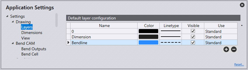
Name – This is the name of the layer to which the geometry will be used.
Colour – A spectrum of colours can be chosen here to show different elements in the part.
Linetype – This is the type of line to be used to show the layer, represented through dots and dashes.
Visible – Turn this option on for the layer to be visible or turn it off for the layer to not be seen in the drawing.
Use – This is the use of the element of the layer. The different options available are:
- Standard – This is the standard layer to be used for CAM.
- Auxiliary – An auxiliary layer, not to be used for CAM.
- Mark – Any entities in this layer will be marked, not cut.
- Approach marker – Point entities indicating laser approach position.
- Sequence marker – Text markers indicate the sequence order of contours.
- Forming centre – Centre mark for forming (point or small L).
- Forming footprint – The outline (footprint) of a forming.
- Evaporate – This layer would be used to distinguish film burning.
- Dot marking – This layer would be used for QR codes.
- Info – This is an information-only layer.