Part Workflow
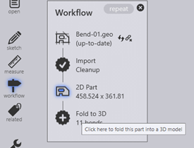
Depending on the type of drawing that has been opened and the program level, additional menus and/or functions are available on the screen interface. The workflow panel represents a lot of information and operations in a compact, graphical form. Much of the time, this will serve as the central hub when working with parts. The Workflow panel is a central hub where you can direct all these movements. Upon opening a part, click on the Workflow icon found on the left of the launch screen or use the shortcut key W to display the workflow panel.
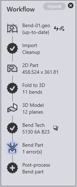
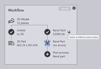
There are different types of nodes in the workflow diagram.
- The part data is pushed between these nodes by various processes, and these processes are represented in the workflow panel using the 13-pointed star icons.
- Part view nodes represent the various types of processing one could do on a part. Clicking on these nodes switches the part to that view and the set of operations available on the part is representative of that view.
- The part view nodes also have shortcut keys. These can be seen by hovering the mouse over the icons. Shortcut keys will allow quick navigation through the workflow. Key sequences can be used, such as 2, 3, B and L to switch between these views.
- Completed processes will have a checkmark displayed inside them. Processes not yet completed will have a cross displayed inside, click on these process nodes to complete the process.
Available Process Nodes
A 13-pointed star with a + inside represents a processing step that is now available. For example, it could be the folding of a 2D flat into a 3D model or assigning laser tech. Moving the mouse over such a node displays a tooltip that explains what the node will do.
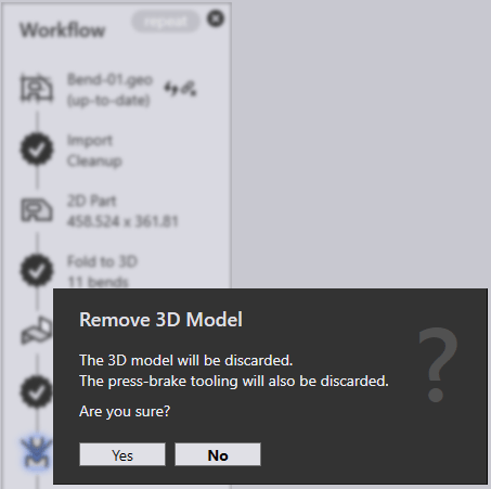
Ctrl and click on a node to delete the process data. A prompt will be given before the deletion is carried out.
Auxiliary Commands
Many nodes have small icons near them, providing auxiliary commands. These commands provide some functionality that is related to that node. The auxiliary icons near each technology node typically allow the selection of a different machine and tool up for that machine. Icons near the output nodes will open the various outputs from a processing node (Reports or NC-code).
Source File Tracking
Most processing starts by importing CAD data (either 2D or 3D). The parts that are built from this CAD data can continue to track these source parts. When a part is opened, it can check if the original CAD file from which it was created has been changed in the meanwhile. If it has, the part is now out-of-date, and this can be seen in the workflow panel.
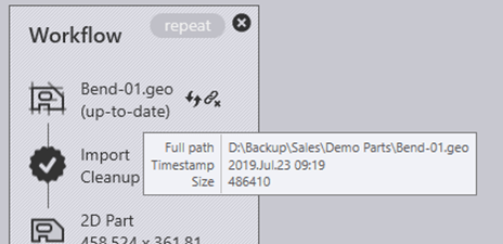
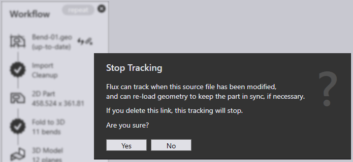
The Refresh Part icon near the source part node will re-import the CAD geometry and rebuild the part. The Break Link icon will stop tracking the original CAD geometry. This might be useful if the original CAD file exists on a removable medium or on a remote drive that may not be accessible in the future. To do this, click on the break-link auxiliary icon near the source part node. This will bring up a prompt to stop tracking the source file.